
EMBEDDED / UCT · EEE3096S / 2023
Signals, timing and the physical world
Connect waveform samples to hardware timing: collaborative STM32 work with timer-triggered DMA, PWM and analogue-input control.
UCT / COURSE CONTEXT / 2023
EEE3096S · Embedded Systems II
Embedded architectures, firmware/software stacks and system modelling. The practicals shown here focus on peripherals and signal generation.
2026 PORTFOLIO RECREATIONS
The signal deskENGINEERING PERSPECTIVE
Inside the work
Use hardware timing and data movement to produce a repeating output without writing a CPU-driven sample loop. The work links discrete waveform tables to microcontroller peripherals and physical-interface constraints.
- Embedded C / STM32
- Configure registers and interrupt-driven peripheral behaviour.
- Timers / DMA / PWM
- TIM2 events transfer lookup values into TIM3 CCR3; related practicals connect ADC input and LCD interaction.
Choose a table
Select the submitted sine, sawtooth or triangle sample array.
- Sample cadence
- The timer event rate and table length jointly determine the nominal waveform repetition rate.
- DMA
- A peripheral event can move data from memory to a register independently of a software loop.
- Interrupt design
- Blocking delays in an ISR and DMA restart behaviour affect responsiveness and need hardware review.
What the demonstration establishes
The browser instrument illustrates source-derived lookup values and cadence. It is not an oscilloscope measurement, firmware emulator or fresh board test.
Evidence behind this page
Collaborative hand-ins and C excerpts, including additional ADC/SPI context. Missing board/HAL/LCD files prevent a complete firmware rebuild.
What it is
Embedded practicals exploring waveform generation and analogue-input control on a microcontroller, with LCD and interrupt interaction.
Why it was built
Understand how microcontroller timing and data movement produce a physical output without a CPU-driven sample loop.
My contribution
Collaborative practical by Azhar Abdool and a named partner, supported by the hand-in. The report does not divide peripheral/module ownership, so no sole-author claim is made. ST vendor headers retain their separate terms.
How it works
A timer-driven DMA transfer writes waveform lookup-table values to the PWM compare register. A related practical samples ADC input and updates PWM behaviour.
- 01Waveform LUT
- 02Timer trigger
- 03DMA
- 04PWM compare register
- 05Signal output
Technical implementation
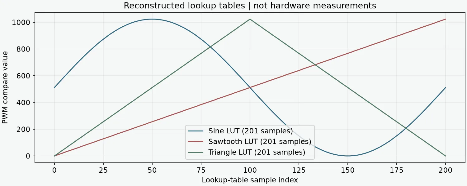
- The source defines 201-sample sine, sawtooth and triangular lookup tables and a nominal 8 MHz timer clock / 10 Hz signal configuration.
- TIM2 output-compare events request DMA transfers from the selected table into TIM3 CCR3, changing the PWM duty cycle.
- An external-interrupt handler switches tables and updates the LCD. The related ADC practical demonstrates input-dependent PWM control.
- The supplied excerpt contains line-wrapped numerical literals and lacks board/HAL/LCD dependencies. The plot repairs whitespace only for documentation; it is not a rebuilt firmware or oscilloscope trace.
A peripheral, made visible
Visual evidence
Results & evidence
- Original C source demonstrates peripheral configuration and waveform tables.
- Separate practical source documents ADC sampling and PWM control.
Engineering challenges
Peripheral clocks, sample cadence and destination registers must align. Blocking delays inside an interrupt handler and DMA restart behaviour deserve review.
Scope & limitations
Source excerpt only. Original board headers, HAL/startup/linker files and LCD support are missing from the selected folders. Hardware execution and oscilloscope measurements were not performed during cleanup.
What I learned
Timer-triggered transfer, interrupt behaviour and the relationship between numerical samples and PWM hardware. Additional collaborative hand-ins corroborate SPI memory commands and the ADC/TIM3/LCD peripheral exercise; neither is a new hardware retest.
What I would improve now
Recover the exact board project and vendor licence, replace blocking ISR delays with deferred state changes, validate DMA mode and measure the actual output on hardware.